
Manhole installation manuals
MANUAL FOR OPTIMUM ON-SITE INSTALLATION OF PRECAST CONCRETE ELEMENTS FOR THE EXECUTION OF MANHOLES
The installation of a manhole on-site from the different elements provided by Prefabricados Alberdi S.A. (base modules, extension modules, tapered modules and slabs) must be carried out following a number of guidelines, indicated below, that guarantee its tightness once assembled.
1.- Placement of base module
The base module must be placed on the flattest, most horizontal surface possible, that will allows the installation of the manhole to continue up to the surface with minimal deviation from the vertical. It is key for correct construction of the manhole that this piece is properly seated.
2. – Joint between the different elements that make up the manhole
In a manhole made up of precast concrete elements by Prefabricados Alberdi S.A., the following types of joints are possible:
- Base module – extension module
- Extension module – extension module
- Extension module – slab
- Extension module – tapered module
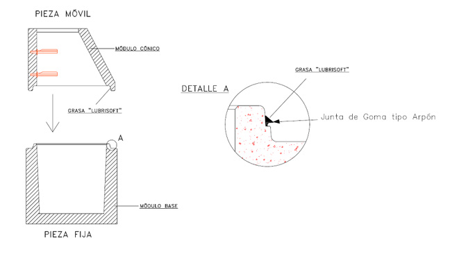
In all of them, the method for placing the elements is the same: insert the male or spigot of the lower part (fixed) into the female or bell of the upper part (mobile).
Prior to this step, you must fit a rubber “harpoon” gasket type in the bell of the lower part and lubricate generously with “LUBRISOFT” grease, also provided by Prefabricados Alberdi S.A. Also smear this product in the bell of the upper part to guarantee this lubrication (see sketch).
It is VERY IMPORTANT to lower the mobile part vertically with precision to prevent the rubber gasket getting caught and moved from its working position.
In addition to this gasket, in projects with the strictest requirements for tightness, another butyl gasket to the one mentioned previously, which will further ensure the tightness of the different joints. See the particular case for projects with a water table, which also require the use of this double gasket.
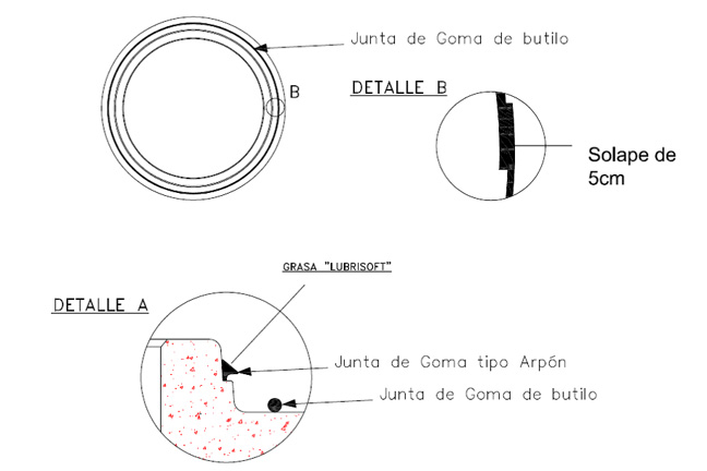
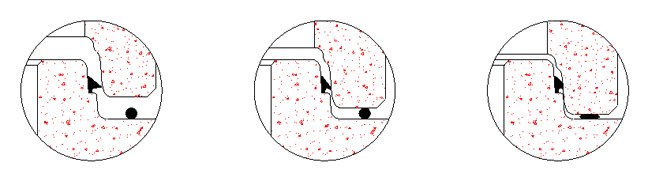
This butyl additional gasket must be positioned on the horizontal face of the bell of the lower part, approximately at the centre, to be crushed by the upper part. If this is not correctly positioned, it would compromise the tightness of the joint and, consequently, the manhole as a whole (see sequence).
3.- Placement of an intermediate safety slab
According to current legislation, the maximum free fall permitted for a worker, without protection, is 2 m. Given the existence, on many occasions, of manholes that exceed this height, it is necessary to an intermediate part between the different elements that comprise it to break any possible falls.
At Prefabricados Alberdi, we have a product that may be used for these cases, called the SAFETY SLAB.
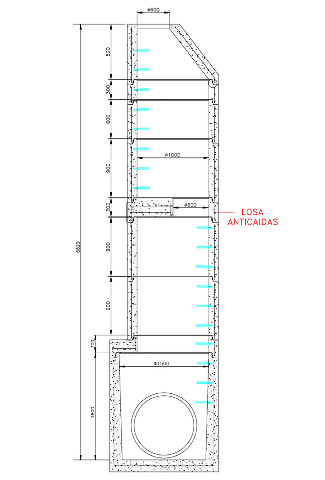
It is a slab that allows the diameter of the manhole to continue (Ø1000mm and Ø1200mm) but one must pass through holes of Ø600mm. Thus, should a worker fall, this component would break his or her fall.
See in the following sketch how Ø1500mm manholes look with reduction to Ø1000mm and with a total height greater than 6m.
4.- Job of the connection pipes(s)
Depending on the connection pipes and the type of joint with the manhole, the following cases can arise:
- Connection of concrete pipes through perforated holes
- Connection of concrete pipes through bell-shaped holes
- Connection of plastic pipes through perforated holes
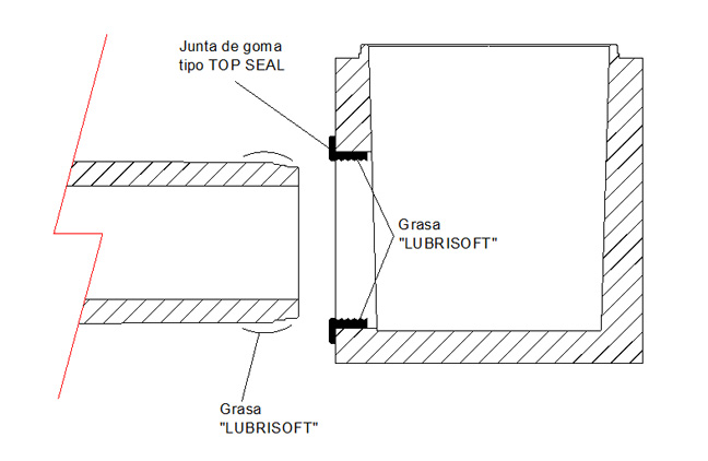
4.1.- Joint with manhole – concrete pipes through perforated holes
To guarantee the tightness of this joint, you must fit a “TOP SEAL” connection gasket in the holes in the manholes, lubricating it adequately. Also apply lubrication to the bell area of the pipe to facilitate its insertion into the manhole (see sketch).
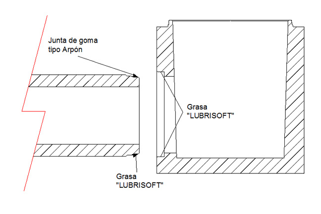
4.2 – Joint with manhole – concrete pipes through bell-shaped holes
In this case, the joint between the pipe and the manhole is identical to that which will be made between two consecutive pipes. The rubber “harpoon” gasket must be fitted in bell part of the pipe designed for this and lubricate it along with the bell in the hole in the manhole to facilitator the watertight placement of the pipe (see sketch).
4.3.- Joint with manhole – plastic pipes through perforated holes
For this type of joint, we can in turn differentiate two cases.
- For plastic pipe with a corrugated exterior
- For plastic pipe with a smooth exterior
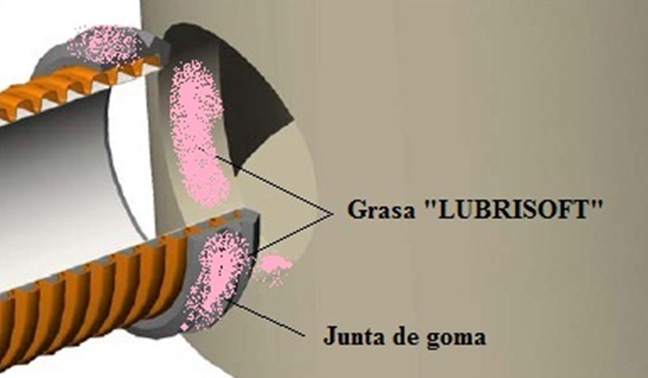
4.3.1.- Joint with manhole – plastic piping with a corrugated exterior
The watertight joint between plastic piping with a corrugated exterior and the manhole must be made with a rubber gasket that it is placed in the bell of the pipe, on top of the corrugation. After applying the corresponding lubrication to both the pipe and the walls of the holes, you must gradually insert the pipe until you verify that as many ridges as possible of the gasket are in contact with these walls (see sketch).
Example of INCORRECT placement
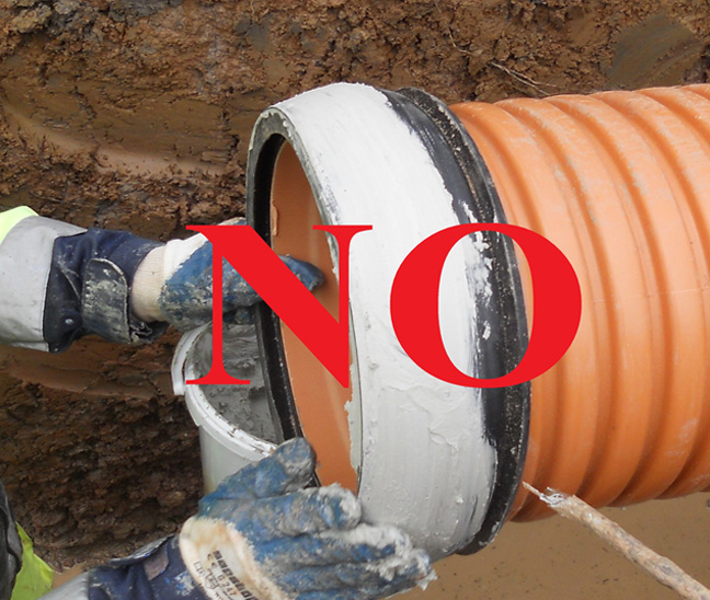
Example of CORRECT placement
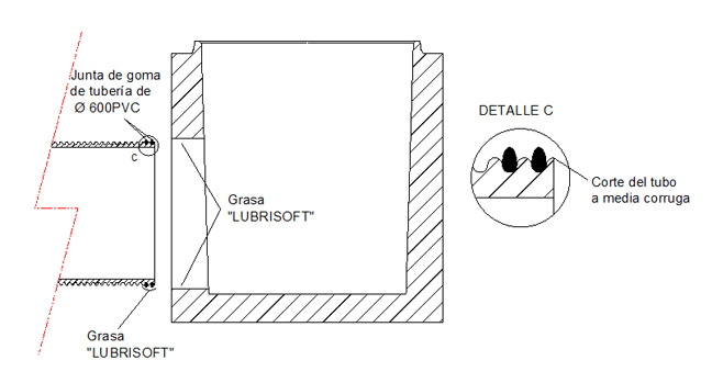
There is a special case that is an exception to the above point. This is the joint between a corrugated PVC pipe of Ø600 and the corresponding manhole. This should be made using the rubber gasket supplied by the manufacturer of the pipes. Specifically, cut the pipe in the middle of one of its corrugations and fit two gaskets in the next two consecutive corrugations nearest the end you have cut. Once you have done this, like for other corrugated pipes, apply “LUBRISOFT” grease to both the exterior of the rubber gasket and to the wall of the hole (see sketch).
4.3.2.- Joint with manhole – plastic piping with a smooth exterior
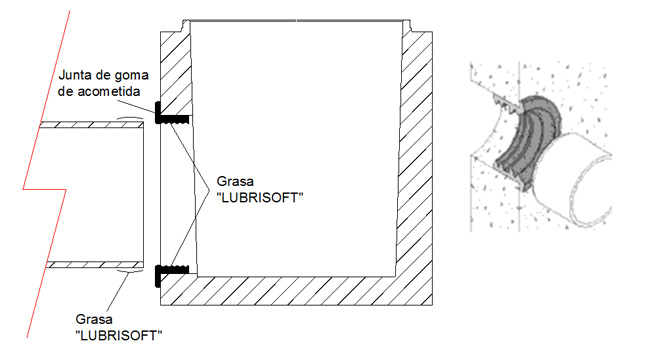
In this case, the difference with the previous case lies in the gasket, which must be fitted in the manhole and not the pipe. For this reason, the lubrication must be applied in the bell area of the pipe that you are going to insert into the manhole and on the lip of the gasket itself (see sketch).
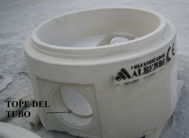
VERY IMPORTANT NOTE: When you are inserting plastic pipes into holes in the base modules with the precast water cradle, you must make sure that this pipe is inserted up to the concrete limit to guarantee the sealing gasket works properly (see photo).

Nous utilisons des cookies et des tiers, pour l'analyse de la navigation des utilisateurs. Si vous continuer à naviguer, considérez que vous acceptez l'utilisation. Vous pouvez modifier les paramètres ou obtenir plus d'informations ici.

Arriandi auzoa, 1
48215 Iurreta - Biscaye (Espagne)
Tél. : +34 94... voir téléphone
Fax : +34 94... voir fax
Prefabricados Alberdi - Copyright 2012 | Avertissement légal | Protection des données | Plan du site | Cookies


Site web conçu par 
et développé par DMacroweb